Sika Waterbar®-940
(former MSeal 940)
Centrally and externally placed PVC Waterstops
Sika Waterbar®-940 is a range of centrally placed and externally placed PVC Waterstops extruded from high grade PVC compound.
- Permanent flexibility
- Homogeneous waterbar
- Suitable for low to medium levels of hydrostatic water pressure
- Resistant to all natural mediums in soil and groundwater
- Robust products designed for handling and installation on site
- Suitable for thermal welding on site

Usage
Sika Waterbar®-940 is designed to provide a complete sealing network for expansion and contraction/ construction joints in water retaining and water excluding in-situ concrete structures. The profiles are supplied in straight lengths to be butt jointed on site. Factory made intersections are available for complex junctions.- Canals/ culverts
- Water tanks
- Reservoirs
- Dams
- Sewerage Treatment Plants
- Liquid retaining vessels
- All cast in-situ concrete structures to retain or exclude water
Advantages
- Permanent flexibility
- Homogeneous waterbar
- Suitable for low to medium levels of hydrostatic water pressure
- Resistant to all natural mediums in soil and groundwater
- Robust products designed for handling and installation on site
- Suitable for thermal welding on site
Packaging
Standard Profile: | Width (mm) | Roll size |
IEJ (Internal Expansion Joints) | 150 , 200 and 250 | 15 m |
ICJ (Internal Construction / Contraction Joints) | 150 , 200 and 250 | 15 m |
EEJ (External Expansion Joints) | 150 , 200 and 250 | 15 m |
ECJ (External Construction / Contraction Joints) | 150 , 200 and 250 | 15 m |
Special profile with 10 mm thick: | ||
ICJ/X | 250 | 10 m |
IEJ/X | 250 | 10 m |
EEJ/X | 250 | 10 m |
ECJ/X | 250 | 10 m |
- 320 mm and 350 mm special size available for some profiles, please contact Sika presentative.
- For detailed shape and illustration of waterbar options, please refer to General Method Statement.
Colour
Blue or Yellow
Product Details
CERTIFICATES AND TEST REPORTS
- ASTM D 412 (Tensile/ Elongation)
Composition
PVC-P (plasticized)
Shelf life
Up to 60 months from date of production.
Storage conditions
Store in undamaged, unopened, original sealed packaging in dry conditions at temperatures between +5°C and +35°C. Protect from direct sunlight, heat and moisture.
System structure
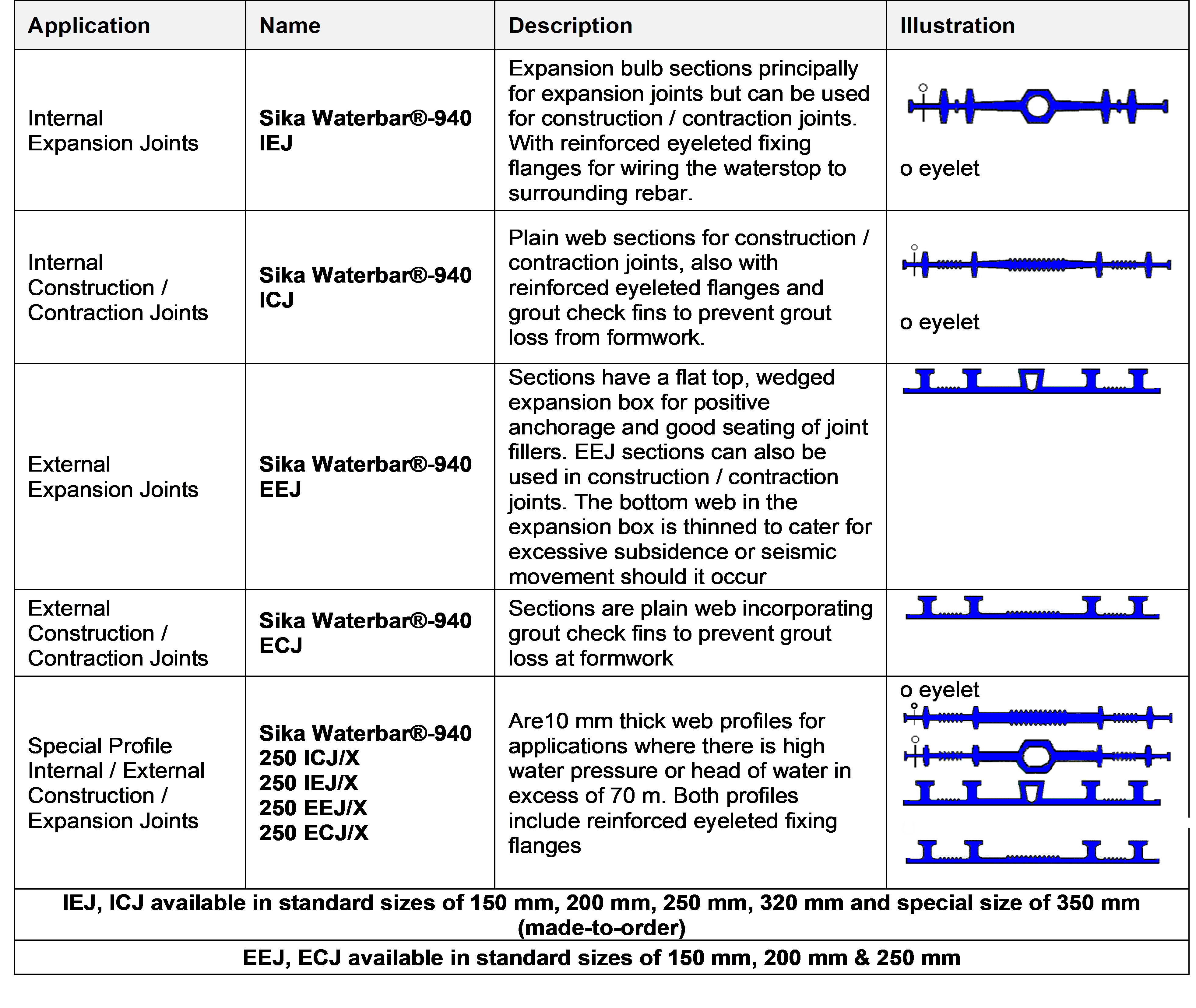
Sika Waterbar®-940 - Internal / External - Construction / Expansion Joints
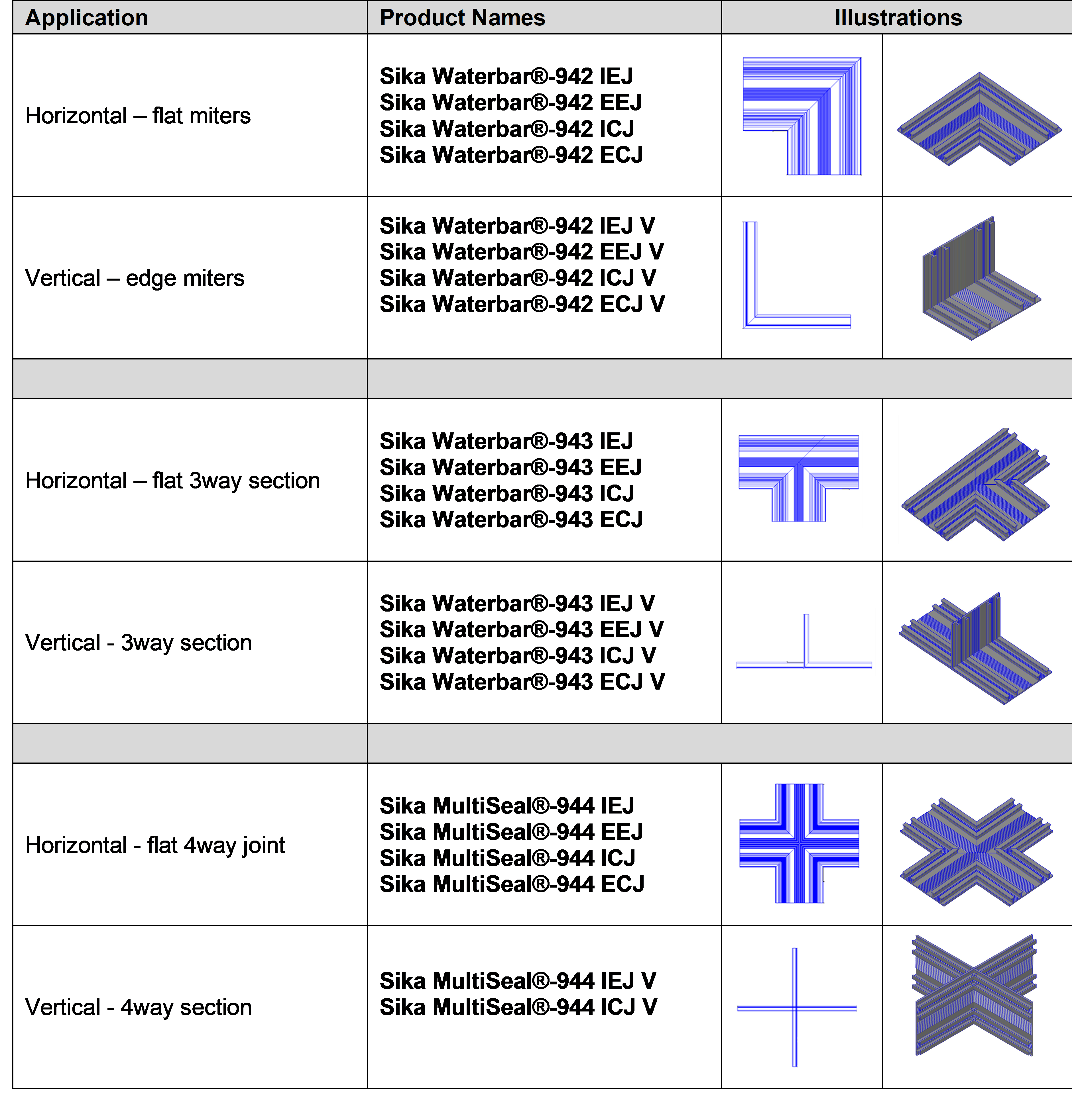
Intersection Pieces / Junctions:
Standard factory produced welded intersections are available for all Sika Waterbar®-940 profiles as detailed below"
Shore A hardness
80- 85 | (ASTM D2240) |
Tensile strength
~15 N/mm2 | (ASTM D412) |
Elongation at break
~300 % | (ASTM D412) |
Application
Ambient air temperature
+5°C min. / +35°C max.
EQUIPMENT
- Heat welding equipment is required to enable site jointing to be carried out efficiently.
- Ensure that the mating surfaces of the waterstop are accurately aligned while the heater blade heats the waterstop to the necessary temperature for jointing.
APPLICATION
- Sika Waterbar®-940 ICJ & IEJ profiles must be installed so they are securely held in the correct position whilst the concrete is poured.
- The concrete must be fully and properly compacted around the waterstops.
- Where reinforcement is present, an adequate clearance must be left between this and all waterstops to permit proper compaction of the concrete.
- The eyelets in the reinforced flanges of the ICJ and IEJ profiles allow them to be wired to the surrounding reinforcing steel. The eyelets are an integral part of the profiles and being placed outside the outer valves cannot create a water path around the profile or impair the efficiency in performance in any way. See typical detail below.
- Sika Waterbar®-940 ECJ & EEJ profiles when used on ground slab blinding concrete where a permanent, firm and stable support is given usually require no fixing.
- The profile is simply laid centrally over the line of the joint to be formed.
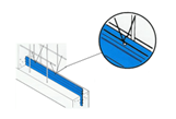
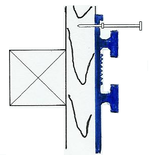
- Fixing to vertical shuttering is simplified by nailing with double headed nails through the outer reinforced flange to provide a firm fixing as shown below.
HEAT WELDING OF WATERSTOPS
|
|
- Make sure that the heater blade is clean, plug it into the correct voltage electricity supply and leave in a safe position to warm up.
- Ensure that the ends of the waterstop to be jointed are of the same width and profile; clean them with water and dry them.
- Clamp them in the correct profile slots of the jig provided and cut both ends off square with a sharp knife, flush with the faces of the jig.
- Note: An allowance must be made for waste and for the 5 to 10 mm that will be taken up by melting when calculating the length of waterstop required.
- Loosen the jig and slide them back so that approximately 10 mm of each waterstop end projects and then clamp the jig tightly in position.
- Position the heater blade on the bars between the jigs and slide them together until the waterstop ends are pressed firmly against the sides of the blade. The PVC should melt without burning or charring. Hold the jig firmly in position until a bead of molten PVC approximately 3 mm in diameter appears along either side of the heater blade.
- Slide the jig apart a little and remove the heater blade with an upward movement. This will ensure that it takes as little PVC as possible with it. Quickly joint the molten ends by sliding the jig together and exerting pressure. Approximately 20 seconds to allow the molten PVC to fuse completely. Switch off the heater blade. While it is still hot, clean thoroughly with emery paper or a wire brush ready for the next joint. Unclamp the jig and carefully remove the waterstop. Do not flex the joint until it has cooled. The joint is now complete. When cold, test it by flexing the waterstop several times.